This post essentially gives some basic information on a typical Petrol Engine management system along with information on inputs from sensors and other sources, outputs from the system to drive actuators, indicating lamps, heaters and spark plugs and data interfaces through CAN bus.
Engine management system (EMS) – Petrol Engines :
The function of EMS is essentially to ensure quick response to a driver’s input of required thrust as input through the accelerator pedal, , optimum fuel consumption under all driving conditions within the performance parameters while continuously monitoring the system to sense faults or potential faults. The EMS uses a set of sensors which input the signals of different system parameters, a set of actuators which are driven by the EMS to achieve the control objectives stated above. A quick reference block diagram in Fig 7.1.2 gives the inputs and outputs comprising the EMS for a petrol engine is given below. The normal power supply interfaces namely Battery + , Ignition +, the system ground, the sensor ground are not explicitly shown in the interface diagram.
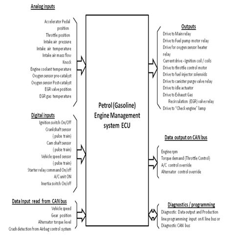
7.1.2 Sensors, switches, actuators and outputs and interfaces for EMS for petrol engines
An overview of the sensors , switches which are inputs and the actuators and other outputs driven by the Petrol engine management system is given in the form of reference tables below :
| Sensors / switches and basic principle of operation | Salient Electrical details |
| Accelerator pedal position sensor : The angular motion of the accelerator pedal is converted to an equivalent voltage through a potentiometer; in view of the constant wiping action of the moving contact of the potentiometer contactless sensors using the Hall effect principle have been developed. | Typically the range of angular movement is about 70 deg. The supply to the sensor from the ECU is 5 volts and the output voltage output of the potentiometer is from 0.5 volts to 4 volts over the range of movement in the hall effect a Hall effect IC is used as part of the sensor which has the magnetic circuit. The signal which is normally at mV levels is processed and given out at a higher level like in a potentiometer |
| Throttle position sensor : This is similar in principle to the acceleration pedal position sensor and differs only in the packaging to suit the mounting, linkages and the physical environment. | The electrical specifications and interfacing details are similar to that of Accelerator pedal position sensor |
| Intake air pressure sensor : The pressure is sensed by means of a circular diaphragm held in position at the rim ; the diaphragm deflects on one side when exposed to pressure on the other side. The strain / deformation due to the deflection is converted into change is resistance of a strain gauge strip. | It is mounted at the air intake manifold ; the sensor is supplied with a voltage of 5 volts from the ECU and the strain gauge resistance change is converted into an corresponding voltage ; the typical pressure range is 1 atm to 5 atm and the output voltage level is typically 0.25 v to 4.85 V. |
| Intake air temperature sensor : It is normally a thermistor with its resistance sensitive to temperature change with a negative temperature co-efficient , the resistance decreasing with increasing temperature. It is a highly non linear sensor and the electronic signal processor has the linearizing and scaling / calibration function built in for further use. | For a temperature range from – 20 °C to + 120 °C the resistance change will typically be from 40kΩ to 0.2kΩ with the rate of change in relation to temperature change at higher temperature much shallower. The sensor is formed in a potentiometer mode in series with a fixed resistor and so as the temperature drops the thermistor resistance drops and hence the voltage output. |
| Intake air mass flow sensor : This is a direct measure of the air mass flow which has a relation to the oxygen available for combustion and the ECU adjusts the fuel supply accordingly to get the most efficient combustion and least toxic emissions .The mostly used air mass sensor is a hot wire type where a hot wire supplied by an electric current source is placed in the path of air intake. When the air mass flowing in is high the hot wire cools and its resistance changes and the current supplied to the hot wire is now increased to bring the hot wire back to its normal preset temperature and the current fed in this is a measure of the air mass flow. | The flow rate usually met with are of the order of 0 to 1000 kg per hour. The supply voltage is 5 volts; the sensor is designed to give a corresponding output of 0 volts to 4.8 volts ; it rises steeply and tapers off in a near exponential mode. |
| Knock sensor : Knocking is a phenomenon which occurs inside the engine cylinder due to detonation of the un-burnt fuel-air mixture ; the shock waves created by ‘knock’ are much stronger in comparison with the waves generated by the normal combustion process. The sensor employs a piezoelectric crystal pressured by a diaphragm which deflects when there is a shock on its mounting. The piezoelectric crystal generates electric charge displacement which is picked by a charge amplifier to convert into a voltage. | The knock sensors are mounted on the cylinder head or on the engine housing and generate a voltage of > 30mV which is used by the ECU as detection of ‘knock’ so that it takes overriding corrections to reduce the fuel input. |
| Engine coolant temperature sensor | It is similar to the Intake manifold temperature sensor of the thermistor type with a negative temperature co-efficient |
| Oxygen sensor (Lambda) sensor – Pre-catalyst : The sensor is based on a Nernst’s cell (named after an inventor), which is essentially a fuel cell where a central core is exposed on one side to the exhaust gas and on the other side to the atmospheric air and depending on the difference in the oxygen concentration on the two sides a voltage across the terminals gets developed . If the air fuel mixture is near the stoichometric value of 14.7 ( the λ = 1 ) output tends to shift constantly between 0.2 V and 0.8 V with an average value around 0.45 V. For the sensor to operate properly the cell needs to be maintained around 300 ° C and this is done through an electrical heater which is part of the sensor assembly. | The sensor has a four terminal connector normally; two terminals for the heater connection and two for the sensor output. Some designs use the exhaust body as the return ground terminal ; in such a case a three terminal connector is used. |
| Oxygen sensor (Lambda) sensor – Post-catalyst : The principle is the same as the pre-catalyst sensor but the mounting and packaging may be different to suit the location. | |
| Crankshaft sensor : This is used to sense the rotational speed of the crankshaft and thereby the engine rpm. In addition this sensor is also used as a reference for ignition timing . The commonly used principle is Hall effect. The sensor is placed near the periphery of the crankshaft with the sensor surface about a cm in diameter faces the crankshaft surface. A cylindrical button of steel or a flat piece acting as a tooth ( magnetic) is embedded on the crankshaft near the periphery such that the surface of the button / tooth comes exactly in front of the sensor with a gap of 2 to 3 mm. The sensor senses the button/tooth when in proximity through change in the flux in its magnetic circuit which in turn changes the electrical impedance in another axis of the hall effect sensor. As the crankshaft rotates the sensor generates a series of pulses one per revolution. Thus the rate of the pulses is used as a measure of the engine rpm. The position of the button or tooth is precisely related to the TDC of the engine and so can act as a time marker for when precisely to send ignition signal or inject the fuel. | There are three terminals to the sensor ; two for the supply and the third for the pulse output when the crankshaft sensing piece comes in proximity to the sensor surface. The power supply lines are part of the engine wiring harness and these connections can be spliced from those lines. The output is wired to the ECU connector as an input. |
| Cam shaft sensor : The crank shaft sensor gives the signal to the ECU to control the ignition timing and which cylinder to fire is decided from the signal from the cam shaft sensor which indicates which cylinder is in the compression cycle and which is in the exhaust cycle. Cam shaft and crankshaft sensor signals are used by the ECU to determine which cylinder to fire and when to fire. | The cam shaft works on a similar principle to that of the crankshaft sensor and interfaced similarly to the ECU through the engine wiring harness. The mounting and the packaging of the two sensors are different just to suit the location and for accessibility. |
| Vehicle speed sensor : The vehicle speed sensor is normally located at the drive output of the transmission unit. It consists of a non contact sensor which senses the presence of teeth in proximity to its sensing surface. It is similar to the crankshaft sensor and uses the Hall effect principle. The toothed wheel’s teeth sequentially come in proximity and go away from proximity of the sensing surface and this generates a train of pulses at the output terminal of the sensor. The rate of pulses generated by the sensor as its output is a measure of the vehicle speed since the toothed wheel is driven from the transmission unit’s output, which also drives the wheels of the vehicle. | The electrical specifications and interfacing details are similar to that of crankshaft sensor . In some vehicle system the wheel speed sensors which are part of the anti skid braking system (ABS) is used to generate the vehicle speed signal ; the ABS ECU computes and generates the vehicle speed signal and shares it with other vehicle systems like Engine management, Transmission controller, Electric power steering controller and the instrument panel. |
| Crash detect switch / inertia switch : This is a bi-state switch which under normal conditions is closed; it has a suspended mass held in position by a set of springs in all directions ; this is normally mounted on the body of the vehicle in the engine compartment near the fuel pump ; when a crash occurs or when a very sudden jerk takes place to the vehicle causing a sudden displacement of the mass to the other position when the switch gets opened. This switch command is used by the ECU to switch off the fuel pump and cut off the fuel supply to the fuel lines so that the chances of fuel catching fire is reduced significantly. | This is wired to the ECU through the engine wiring harness |
Actuators and lamps – basic principle of operation & salient electrical details
| Main relay : This is driven from the Engine ECU when the ignition switch is turned on the ECU switches on the Main relay to on state. This relay is the main control relay to run / control the engine. The relay coil typically draws about 150 mA from the ECU and the contacts of the relay are capable of handling currents of the order of 20 amps . |
| Fuel pump : It is driven by the ECU in response to an input from the starter relay indicating an intent to start. Once started the fuel pump motor remains on till the ignition switch remains in the ON state and consumes typically around 12 amps. |
The figure below gives a typical control circuit for the main control relay for a engine control system.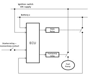
|
||
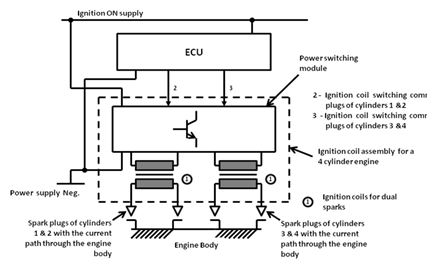
Fig 7.1.4 Typical Ignition system schematic for a petrol engine
| Throttle control motor : This is a part of the control of the EMS in response to the vehicle driver’s demands or intentions as sensed by the accelerator pedal position sensor. When the accelerator pedal position changes the sensor sends a corresponding signal to the ECU; the ECU correspondingly drives the throttle position motor which is normally a permanent magnet DC motor. |
| Oxygen sensor heater : The Oxygen or Lambda sensor acts as a fuel cell to generate the two main levels of output , one when the stoichiometric value is below 1 and another state when it is above 1. To function as a fuel cell the sensor core needs to be around 320 °C. A heater coil is embedded in the sensor and the ECU drives the heater of the sensor as one of its outputs. The heater coil typically will draw around 2 amps from the ECU. |
| Fuel injectors : These are essentially electromagnetic solenoids precision designed specifically to handle trillions of linear in and out motions to act as delivery nozzles on the application of voltage pulses from the ECU. The time at which they are switched on in a engine cycle and the period for which they are on decide the combustion process based on the load on the engine. |
| Canister purge solenoid valve : This valve when switched on, purges the vapour collected in the carbon canister from the evaporated fuel , into the fuel inlet to enrich the mixture of air-fuel as sensed by the lambda sensor and also to limit the pressure of collected vapour in the canister from exceeding limits. |
| Idle speed actuator : With the accelerator position in idle position the throttle valve is fully closed and to keep engine running the idle speed control valve is used to bypass the throttle valve through a solenoid operated metering valve which moves the plunger of a metering valve to let a controlled quantity of air into the engine. This controls the idle engine rpm, helps control the exhaust emission and the harshness in terms of vibration and idle speed noise. The ECU controls the current to the idle speed actuator solenoid which in turn controls the air input at idle. |
| EGR valve : Exhaust Gas Recirculation is a method by which the combustion temperatures are sought to be reduced in order to reduce NOx emissions in the exhaust which are caused by Nitrogen combining with Oxygen to create NOx at high temperatures > 2500 °C . EGR valve is controlled by the ECU and opens a path for part of the exhaust gas, which is inert , to be re-circulated at the inlet; the re-circulated gas occupies some volume of the engine chamber thus reducing the volume of the Air-fuel mixture ; this reduces the combustion temperature. The ECU brings EGR into play only above idle rpm since at low speeds EGR tends to make the combustion unstable and rough. |
| “Check Engine” lamp : This lamp, which is either amber or red colour, is provided on the instrument panel placed in front of the driver to indicate a fault in the engine system which needs to be attended to . A steady indication means there is a minor fault like some sensor connection is intermittent or lose, the oxygen sensor is not sending the right signals. A flashing indication means a serious fault condition which needs urgent attention which if left uncorrected could lead to major failures like engine seizure or catalytic converter or some parts getting permanently damaged. |
ECU data elements as input and output on the CAN data bus
One of the main advantages of use of a networked data communication on the vehicle as already mentioned earlier is to eliminate the repeat use of sensors for measurement of the same parameter like, engine rpm, engine temperature, vehicle sped etc., in different control units; the data on one parameter from one of the units may be required for more than one system on the vehicle and this data can be processed by the ECU of one of the systems taking input signal from a sensor and the processed value can be placed on the CAN bus which is part of the vehicle network. The data on the bus is thus used by the other ECUs. Apart from eliminating redundant sensors and thus improving overall reliability, such a sharing of sensors reduces wiring and complexity.
Typically an engine ECU processes and shares the following signals / data placed as outputs :
- Engine rpm (speed) value – used by Transmission control unit, Instrument cluster and Body Control Module
- Throttle position value – used by Transmission control unit
Apart from shared data the ECU also sends control signals on the CAN bus to switch off/on Alternator loads and Air conditioning system loads to cater to extra thrust on the wheels depending on the load coming on the engine.
Similarly the engine ECU uses data placed on the CAN bus by other ECUs on the vehicle as inputs. The following are some typical cases of the engine ECU using the data on the CAN bus as inputs :
- Vehicle speed value processed by the Anti-skid Braking System (ABS)
- Gear position value placed on the data bus by the Transmission unit
- Alternator Torque demand value as estimated by the Alternator controller and placed on the data bus
- Air conditioning unit control status as placed by the A/C control unit
Apart from the above data interchanged on the CAN bus the ECU also has an in built programme to present data to a client accessing diagnostic data through the specific diagnostic bus interface provided through a standard 16 pin connector. While the diagnostic connector is mainly used for diagnostics , it is also used to feed vehicle control parameters to specially programme the ECUs to fine tune the ECUs for specific vehicle models and variants so as to realize particular performance requirements.
The next post will be on Engine Management system (Diesel engines).
